
Abstract
The process of removing a ball joint from a vehicle's control arm is a fundamental yet often challenging task in automotive suspension repair. This procedure is necessitated by the wear and eventual failure of the ball joint, a critical pivot point that connects the control arm to the steering knuckle, thereby affecting steering precision and vehicle stability. This analysis outlines a systematic approach for this repair, addressing the two primary configurations: press-in and bolt-on ball joints. It examines the requisite tools, safety protocols, and procedural steps, from initial vehicle preparation and disassembly of the wheel assembly to the crucial separation of the ball joint from the steering knuckle. The core of the operation—extracting the ball joint from the control arm itself using specialized tools like a ball joint press—is detailed extensively. The discussion emphasizes the importance of procedural precision to avoid damage to associated components, such as the control arm or steering knuckle, and concludes with the necessity of post-repair wheel alignment to restore the vehicle's original handling and safety characteristics.
Key Takeaways
- Always prioritize safety by using jack stands, wheel chocks, and proper personal protective equipment (PPE).
- Correctly identify whether the ball joint is a press-in or bolt-on type to select the appropriate tools.
- Use a dedicated ball joint separator or puller to safely detach the stud from the steering knuckle.
- Mastering how to remove a ball joint from a control arm often requires a specialized ball joint press tool.
- Thoroughly clean the control arm bore before installing the new ball joint to ensure a proper fit.
- Always torque all fasteners to the manufacturer's specifications during reassembly.
- Perform a professional wheel alignment after the repair to ensure safety and prevent uneven tire wear.
Table of Contents
- Understanding the Suspension's Anatomy: The Control Arm and Ball Joint
- Step 1: Preparation and Safety – The Foundation of a Successful Repair
- Step 2: Gaining Access – Disassembling the Wheel and Brake Assembly
- Step 3: A Pivotal Moment – Separating the Ball Joint from the Steering Knuckle
- Step 4: Isolating the Component – Removing the Control Arm from the Vehicle
- Step 5: The Main Event – How to Remove the Ball Joint From the Control Arm
- Step 6: The Rebirth – Installing the New Ball Joint
- Step 7: Reassembly, Torque, and Alignment – Restoring Order
- Frequently Asked Questions (FAQ)
- Final Thoughts on the Process
- References
Understanding the Suspension's Anatomy: The Control Arm and Ball Joint
Before we can begin to deconstruct, we must first understand the construction. The relationship between a control arm and a ball joint is a beautiful example of mechanical symbiosis, a partnership that allows for the complex and graceful dance of a vehicle's suspension. To approach their separation without first appreciating their connection would be like trying to solve a puzzle without looking at the picture on the box. It is a task fraught with potential for error and frustration.
What is a Control Arm?
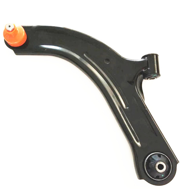
Imagine the control arm as the limb that connects your vehicle's frame to its wheel assembly. This hinged link, often shaped like an 'A' or an 'I', is the primary guide for the wheel's vertical motion (CarParts.com Research Team & McCuistian, 2025). When your car encounters a bump or a dip in the road, the wheel moves up or down. The control arm ensures this movement is controlled, allowing the spring and shock absorber to do their job of absorbing the impact while keeping the wheel in its proper orientation relative to the road and the vehicle's body.
In most modern passenger vehicles, you will find a lower control arm, and in some designs, particularly double-wishbone suspensions, an upper control arm as well. These arms pivot on bushings where they attach to the vehicle's subframe, allowing for smooth, quiet articulation. The other end of the arm, the "outboard" end, is where our focus lies, for this is where it meets the ball joint. Sourcing a high-quality aftermarket control arm is often the best solution when the original component is bent, corroded, or has worn bushings.
The Pivotal Role of the Ball Joint
If the control arm is the limb, the ball joint is the wrist or ankle. It is a spherical bearing enclosed in a socket, functioning exactly like a ball-and-socket joint in the human body. This design is ingenious because it permits movement in multiple planes. It allows the wheel to move up and down with the suspension's travel, while also allowing it to pivot left and right as you steer the vehicle (Customproc, 2025).
The ball joint consists of a threaded stud connected to a metal ball, which rotates inside a lubricated, steel housing. A rubber boot seals the joint, protecting it from dirt, water, and road grime while keeping the essential grease inside. The stud of the ball joint connects to the steering knuckle—the component that holds the wheel hub and bearing. This connection is typically a tapered fit, a design that creates an incredibly strong mechanical lock under pressure but can be a source of great difficulty during disassembly.
Press-in vs. Bolt-on Ball Joints: A Critical Distinction
The method of attachment between the ball joint and the control arm itself is the primary variable that dictates our procedure. There are two dominant designs you will encounter.
- Bolt-on Ball Joints: As the name implies, these are secured to the control arm with bolts or, in some cases, rivets. They are generally simpler to replace. If they use bolts, removal is a straightforward matter of unfastening them. If they use rivets, the rivets must be drilled out or chiseled off, and the new joint is then secured with the supplied bolts.
- Press-in Ball Joints: This is the more common, and more challenging, design. Aqui, the ball joint's housing is pressed into a precisely machined circular bore in the control arm with thousands of pounds of force. This creates an interference fit, where the joint is held in place by immense friction. Removing this type requires a specialized tool to overcome that force. Attempting to hammer it out is often a futile and destructive exercise.
Understanding which type you are dealing with before you begin is paramount. A visual inspection of where the ball joint meets the control arm will reveal either the heads of bolts/rivets or a smooth, seamless metal ring, which indicates a press-fit design.
Step 1: Preparation and Safety – The Foundation of a Successful Repair
Any successful mechanical endeavor is built not on brute force, but on methodical preparation. The time spent here, before a single bolt is turned, is an investment that pays dividends in efficiency and, most critically, in personal safety. Rushing into this process is a recipe for stripped threads, damaged components, and potential injury.
Gathering Your Arsenal: Essential Tools & Equipment
The right tool for the job is not a luxury; it is a necessity. Attempting to use the wrong tool is like trying to write a novel with a crayon—you might make a mark, but the result will be messy and illegible. Your specific needs will vary slightly based on your vehicle and whether you have a press-in or bolt-on joint, but the core list remains consistent.
| Tool Category | Essential Items for Both Joint Types | Additional Items for Press-in Joints |
|---|---|---|
| Lifting & Segurança | Floor Jack, Jack Stands (at least 2), Wheel Chocks, Safety Glasses, Mechanic's Gloves | – |
| Hand Tools | Socket Set (Metric & SAE), Wrench Set, Breaker Bar, Torque Wrench, Hammers (Ball-peen & Sledge), Pry Bars | – |
| Separation Tools | Pickle Fork (Ball Joint Separator) OR Pitman Arm Puller | Ball Joint Press (C-clamp style) with Adapters |
| Fastener Removal | – | Angle Grinder or Air Chisel (for riveted joints) |
| Cleaning | Wire Brush, Brake Cleaner, Shop Towels | Emery Cloth or Sandpaper |
The star of this show, for press-in types, is the ball joint press. This is a heavy-duty C-clamp tool that comes with a variety of sleeves and adapters. It uses the mechanical advantage of a large threaded screw to generate the immense force required to push a worn joint out of the control arm and press a new one in. While it may seem like a significant investment for a single job, renting one from an auto parts store is a common and cost-effective option.
Vehicle Preparation: Lifting and Securing
Your work environment must be stable and secure. A vehicle falling from a jack is a catastrophic failure that can have fatal consequences.
- Park on Level Ground: Begin on a solid, level surface like a concrete garage floor. Never work on soft ground like asphalt on a hot day, dirt, or grass.
- Chock the Wheels: Securely chock the wheels on the opposite end of the vehicle from where you will be working. If you are working on the front, chock the rear wheels.
- Loosen Lug Nuts: Before lifting the vehicle, use a breaker bar to "break loose" the lug nuts on the wheel you will be removing. Do not remove them completely, just overcome the initial torque.
- Lifting: Position your floor jack under a manufacturer-specified lift point on the vehicle's frame or subframe. Never jack on the engine oil pan, transmission, or the control arm itself. Raise the vehicle until the wheel is several inches off the ground.
- Place Jack Stands: This is the most critical safety step. Immediately place a jack stand under a solid part of the frame or subframe near the jack. Slowly lower the vehicle until its weight is resting entirely on the jack stand. The jack is a lifting device, not a holding device. You can leave the jack in place as a secondary backup, but never work under a car supported only by a jack.
Safety First: Personal Protective Equipment (PPE)
The process of how to remove a ball joint from a control arm involves striking metal, dealing with rusted parts, and potential for springs or components to release energy. Protect yourself accordingly.
- Safety Glasses: Non-negotiable. A metal shard, rust flake, or a splash of brake cleaner in the eye can cause permanent damage.
- Mechanic's Gloves: Protect your hands from cuts, scrapes, and grime. They also improve your grip on tools.
- Sturdy Footwear: Steel-toed boots are ideal. A dropped control arm or heavy tool can easily break a bone in your foot.
Step 2: Gaining Access – Disassembling the Wheel and Brake Assembly
With the vehicle securely supported, our next objective is to clear a path to the control arm and ball joint. This involves a careful and organized disassembly of the wheel, brake, and related steering components. Think of it as peeling the layers of an onion to get to the core.
Removing the Wheel and Brake Components
Organization is key here. As you remove bolts and parts, place them in a magnetic tray or a labeled container. This simple habit prevents the frantic search for a missing caliper bolt later on.
- Remove the Wheel: With the lug nuts already loosened, you can now spin them off by hand and remove the wheel. Set it aside.
- Remove the Brake Caliper: Locate the two caliper guide pins or mounting bolts on the back of the steering knuckle. They are typically protected by rubber dust caps. Remove these bolts. Do not let the caliper hang by its brake hose. This can damage the hose, leading to brake failure. Use a bungee cord or a piece of wire to hang the caliper securely from the strut or a frame member.
- Remove the Caliper Bracket (if necessary): In some designs, the caliper bracket may also need to be removed to access other components. It is held on by two larger bolts on the back of the steering knuckle.
- Remove the Brake Rotor: The rotor should now slide off the wheel hub. If it is stuck due to rust, a few firm taps with a hammer on the hub-facing surface can help break it free. Be careful not to strike the braking surface itself.
Disconnecting Stabilizer Links and Tie Rod Ends
Now we move to the smaller, but equally important, suspension and steering links.
- Stabilizer Bar Link: This thin rod connects the end of the stabilizer bar (or sway bar) to the control arm or strut. Its job is to control body roll during turns (AutohausAZ, 2025). It is typically held on with a nut on the top and bottom. You may need to use a wrench to hold the stud itself while you turn the nut to prevent it from spinning.
- Outer Tie Rod End: This is part of the steering system. It connects the steering rack to the steering knuckle. Removing its retaining nut and separating its tapered stud from the knuckle is a necessary step. This process is identical to separating the main ball joint from the knuckle, which we will cover in great detail in the next step.
At this point, you should have a clear view of the control arm, the steering knuckle, and the ball joint that connects them. The stage is set for the most challenging part of the disassembly.
Step 3: A Pivotal Moment – Separating the Ball Joint from the Steering Knuckle
This is often where a straightforward job can turn into a battle of wills. The connection between the ball joint's tapered stud and the steering knuckle is designed to be incredibly secure. Over years of service, heat, pressure, and corrosion forge a bond that can be remarkably stubborn to break. The key is using the right technique to shock the connection loose without causing collateral damage.
The Challenge of the Tapered Stud
Why is this connection so difficult to separate? A tapered stud fits into a matching tapered hole. As the retaining nut (usually a castle nut with a cotter pin) is tightened, it pulls the stud deeper into the hole, creating an immense amount of friction and a mechanical lock. It’s a press-fit, but a conical one. Simply removing the nut does nothing to relieve this pressure. You cannot just pull it apart. The force must be applied in a way that breaks this friction lock.
Before you begin, liberally apply a quality penetrating oil (like PB Blaster or Kroil) to the area where the stud passes through the knuckle. Let it sit for at least 15-30 minutes, or even overnight if you can. This will help dissolve rust and ease the separation process.
Method A: The Pickle Fork (Ball Joint Separator)
The pickle fork is a two-pronged, wedge-shaped tool. It is designed to be driven between the steering knuckle and the ball joint housing, forcing them apart.
- How to Use It: After removing the castle nut, thread it back on a few turns to protect the threads of the stud. Insert the tines of the pickle fork between the rubber boot of the ball joint and the steering knuckle. Then, using a large hammer or small sledgehammer, strike the end of the pickle fork forcefully.
- Pros: It is often effective and relatively inexpensive.
- Cons: This is the "brute force" method. It will almost certainly destroy the rubber boot of the ball joint, meaning you must be replacing the ball joint if you use this tool. It can also potentially damage the steering knuckle or control arm if not used carefully or if the part is severely seized. It is a tool of commitment; there is no turning back once you use it.
Method B: The Hammer Technique
This method seems counterintuitive, but it is often the preferred technique of professional technicians because it is less likely to damage other components when done correctly. It uses the principle of hydraulic shock to break the tapered fit.
- How to Use It: Remove the castle nut completely. Take a heavy hammer (a 2-3 lb sledge is ideal) and deliver several sharp, powerful blows directly to the side of the steering knuckle where the ball joint stud passes through. You are not hitting the stud itself, but the "eye" of the knuckle that surrounds it.
- Why It Works: The metal of the steering knuckle is slightly elastic. The force of the hammer blow momentarily distorts the shape of the tapered hole, breaking the friction lock and causing the stud to pop out.
- Pros: When successful, it is fast and does not damage the ball joint boot (useful if you are removing the knuckle for another repair and plan to reuse the ball joint). It directs force only at the knuckle, minimizing risk to the control arm.
- Cons: It requires confidence and a powerful, accurate swing. It may not work on extremely seized joints. There is a risk of missing and hitting the brake rotor backing plate or other components.
Method C: The Pitman Arm Puller / Ball Joint Separator Tool
This is the most controlled and arguably the "correct" way to perform the separation. These tools use mechanical leverage to press the stud out of the knuckle.
- How to Use It: These tools come in various designs, but the principle is the same. The tool is positioned so that one part pushes down on the end of the ball joint stud while the other part hooks under the steering knuckle. As you tighten the bolt on the tool, it generates a powerful, steady pressing force that pushes the stud out of its tapered seat.
- Pros: It is the safest and most controlled method. It is highly unlikely to cause damage to the stud, boot, or knuckle.
- Cons: It requires having the right tool, which may be an added expense or rental. It can sometimes be difficult to position the tool correctly in tight spaces.
| Separation Method | Effectiveness | Risk of Damage | Tool Cost | Best Use Case |
|---|---|---|---|---|
| Pickle Fork | High | High (destroys boot) | Low | When you are definitely replacing the ball joint and other methods fail. |
| Hammer Technique | Moderate to High | Low (if done correctly) | Very Low | Quick separation when you want to preserve the ball joint boot. |
| Puller/Separator | Very High | Very Low | Moderate to High | The safest, most professional method for any situation, especially stubborn joints. |
Once the stud pops free from the knuckle, you can proceed to the next step. You may need to use a pry bar to push the control arm down slightly to create enough clearance to fully separate the two components.
Step 4: Isolating the Component – Removing the Control Arm from the Vehicle
Em muitos casos, especially with press-in ball joints, the most effective way to perform the service is to remove the entire control arm from the vehicle. This allows you to take it to a workbench where you have better access, leverage, and the ability to use a bench vise and a ball joint press more effectively. While it is sometimes possible to press the joint out while the arm is still on the car, it is often more difficult and time-consuming.
Locating and Loosening the Control Arm Bolts
The control arm is typically attached to the vehicle's subframe at two points via large bolts that pass through rubber bushings.
- Inspection and Penetrating Oil: Before you start, locate these bolts. One is usually at the "front" of the control arm and the other at the "rear". They can be oriented vertically or horizontally. As with every other fastener in this rusty environment, give them a generous soaking in penetrating oil.
- Use a Breaker Bar: These bolts are often very tight and may have thread-locking compound on them from the factory. A long breaker bar will be your best friend here. Position your socket and breaker bar securely on the bolt head or nut.
- Mind the Alignment Cams: Pay close attention to the bolts. Sometimes, one or both of the control arm mounting bolts will have an eccentric washer or "cam" on them. This is used for adjusting the vehicle's wheel alignment (caster or camber). If you see one, it is a good practice to use a paint marker or a scribe to mark the position of the cam relative to the subframe before you loosen it. This will allow you to get the alignment "close enough" upon reassembly to safely drive the vehicle to an alignment shop.
Navigating Obstructions (Axles, Subframes)
Depending on your vehicle's design, removing the control arm bolts might not be a simple affair.
- Front-Wheel Drive Vehicles: On FWD cars, the CV axle shaft often passes directly over or through the control arm area. You may need to carefully maneuver the steering knuckle and strut assembly to create enough clearance to slide the long control arm bolts out.
- Subframe Interference: Sometimes, the subframe itself can block the path of the bolt. In these frustrating cases, you may need to slightly lower one side of the subframe by loosening its main mounting bolts to create the necessary clearance. Consult a service manual for your specific vehicle if you encounter this situation, as it adds a significant layer of complexity to the job.
Final Removal of the Control Arm
Once the two inner mounting bolts are removed and the outer ball joint is free from the steering knuckle, the control arm can be wiggled and pried free from the vehicle. It might be heavier than you expect, so be prepared to support its weight as it comes loose. Now, you can take it to your workbench for the main operation.
Step 5: The Main Event – How to Remove the Ball Joint From the Control Arm
With the control arm on your workbench, you have the space and stability to tackle the core task. The method here diverges completely based on whether you have a press-in or a bolt-on joint.
For Press-in Ball Joints: Using a Ball Joint Press
This is where the specialized C-clamp press tool earns its keep. The goal is to use the correct combination of adapters to push the old joint out of its bore without damaging the control arm.
- Secure the Control Arm: Place the control arm securely in a heavy-duty bench vise. If you do not have a vise, you can work on the floor, but it will be much more difficult to keep things stable.
- Remove the Snap Ring: Inspect the ball joint. Many press-in joints have a snap ring (or circlip) on one side that acts as a secondary retainer. You must remove this snap ring before attempting to press the joint out. Use a good pair of snap ring pliers for this.
- Configure the Press: This is the most crucial part of learning how to remove a ball joint from a control arm with a press. You need to select the correct adapters.
- Receiving Tube: Choose a hollow adapter (the receiving tube) that is large enough for the body of the ball joint to pass through. It must rest squarely on the control arm around the edge of the ball joint, not on the joint itself. This tube creates the empty space for the old joint to be pushed into.
- Pressing Adapter: On the other side, choose a solid or hollow adapter that is small enough to press on the body of the ball joint itself, but not so small that it slips inside or only pushes on the stud. You want to apply force to the strong outer flange of the joint.
- Position the Tool: Assemble the C-clamp press around the control arm with the receiving tube on the side the joint will exit from, and the pressing adapter on the side you will be pushing from. Ensure everything is perfectly straight and centered. An crooked press can damage the control arm's bore.
- Apply Force: Using a large wrench or a breaker bar, begin tightening the main screw of the press. The force required will be immense. You will likely hear loud groans and pops as the friction of the interference fit is overcome. Continue tightening until the old ball joint is pushed completely out of the control arm and into the receiving tube.
For Bolt-on Ball Joints: A Simpler Removal
If you are lucky enough to have a bolt-on joint, the process is far less dramatic.
- Bolted Type: Simply use the appropriate socket or wrench to remove the bolts securing the ball joint to the control arm. If the bolts are rusted, use penetrating oil and be careful not to round off the heads.
- Riveted Type: Factory-installed bolt-on joints often use rivets instead of bolts. These must be destroyed for removal. The most common methods are:
- Drilling: Use a center punch to mark the center of each rivet. Start with a small drill bit and progressively work your way up to a bit that is the same size as the rivet shank. This will drill the head off, allowing you to punch the rest of the rivet out.
- Grinding/Chiseling: Use an angle grinder to grind the heads off the rivets. Alternatively, an air hammer with a chisel bit can make quick work of shearing the rivet heads off. Always wear safety glasses and be mindful of sparks when using a grinder.
Once the fasteners are removed, the ball joint will simply lift off the control arm.
Step 6: The Rebirth – Installing the New Ball Joint
Removing the old part is only half the battle. Proper installation is just as critical for a long-lasting and safe repair.
Cleaning and Preparing the Control Arm
Whether press-in or bolt-on, the mounting surface on the control arm must be perfectly clean.
- For Press-in: Use a wire brush and brake cleaner to thoroughly clean the inside of the bore in the control arm. Inspect it for any burrs, gouges, or damage that may have occurred during removal. If there are minor imperfections, you can use a piece of emery cloth or fine-grit sandpaper to smooth them out. The new joint relies on a clean, smooth surface for a proper interference fit.
- For Bolt-on: Clean the flat mounting surface on the control arm where the new joint will sit. Ensure it is free of rust and debris so the new joint can sit perfectly flush.
Pressing in the New Ball Joint
Installation is the reverse of removal, but requires the same care and precision with the ball joint press.
- Note the Direction: Some ball joints are directional. They may have a specific orientation or a relief that needs to align with a certain part of the control arm. Check the new part and the service manual.
- Configure the Press for Installation: You will again use a receiving tube and a pressing adapter. This time, the receiving tube will support the back side of the control arm, and you will press on the flat bottom of the new ball joint. Never press on the tapered stud.
- Start it Straight: It can be helpful to lightly tap the new joint with a hammer to get it started straight in the bore before applying the press. A very light coating of grease or anti-seize on the outside of the new joint can ease installation, but check the manufacturer's instructions as some advise against it.
- Press it Home: Carefully position the press and begin tightening the screw. Watch closely to ensure the joint is going in perfectly straight. If it starts to cock to one side, back off and reset. Continue pressing until the flange of the new ball joint is seated firmly and completely against the control arm.
- Install the New Snap Ring: If your new joint came with a snap ring, install it now. Also, be sure to install the new grease fitting (if supplied) and fill the joint with the recommended grease until the rubber boot just begins to swell.
Securing a Bolt-on Ball Joint
This is much simpler. Position the new ball joint on the clean mounting surface of the control arm. Insert the new high-grade bolts (which should be included with the joint) and tighten them. It is crucial to use a torque wrench to tighten these bolts to the manufacturer's specified value. Often, these kits will also include new locking nuts.
Step 7: Reassembly, Torque, and Alignment – Restoring Order
With the new ball joint securely in the control arm, it is time to put everything back together. This process is essentially the reverse of disassembly, but with a critical focus on proper torque.
Reinstalling the Control Arm and Wheel Assembly
- Reattach the Control Arm: Maneuver the control arm back into position and insert the inner mounting bolts. If you made alignment marks, try to line them up as best as you can. Thread the nuts on but do not fully tighten them yet. Suspension bushings should always be torqued with the vehicle's weight on them, not while hanging in the air.
- Connect the Ball Joint to the Knuckle: Guide the new ball joint's stud up through the steering knuckle. Install the new castle nut and tighten it to the specified torque. If the stud spins, you may need to apply upward pressure on the control arm with a jack to create enough friction to tighten the nut. Align the slots in the nut with the hole in the stud and insert the new cotter pin, bending the ends to secure it.
- Final Tightening: With the control arm and knuckle connected, place your floor jack under the control arm and raise it until it just begins to lift the vehicle's weight off the jack stand. This simulates the normal ride height. Now, you can use your torque wrench to tighten the inner control arm mounting bolts to their final specification.
- Reassemble Brakes and Wheel: Reinstall the outer tie rod end, link do estabilizador, brake rotor, brake caliper, and wheel. Torque all fasteners to their specified values, especially the caliper bolts and lug nuts.
The Importance of a Post-Repair Wheel Alignment
This final step is not optional. Whenever you replace major suspension components like control arms or ball joints, you alter the vehicle's suspension geometry (Timing-Parts.com, 2025). Even if you marked the cam bolts, it is not precise enough.
Driving a vehicle with improper alignment will cause rapid and uneven tire wear, poor handling characteristics, and can be unsafe. After completing the repair, you must take the vehicle to a professional shop to have a four-wheel alignment performed. This ensures that the camber, caster, and toe angles are all set back to the manufacturer's exact specifications, restoring the vehicle's handling, segurança, and prolonging the life of your new tires and suspension components.
Frequently Asked Questions (FAQ)
Can I just hammer a press-in ball joint out of the control arm? While it might be tempting, it is strongly advised against. The interference fit is extremely tight. Hammering directly on the ball joint can damage the control arm by distorting the bore, making it impossible for the new joint to fit correctly. It is also an ineffective and frustrating method that often fails. Using the correct ball joint press is the proper and safest way.
Do I have to replace the entire control arm instead of just the ball joint? Not always, but it is becoming more common. Many manufacturers now service the control arm as a complete assembly, with new bushings and a new ball joint already installed. This can save significant labor time and ensures all related wear items are new. If your control arm bushings are also worn, or if the arm itself is bent or heavily corroded, replacing the entire control arm assembly is the superior repair.
What are the symptoms of a bad ball joint? Common symptoms include a clunking or knocking noise from the front suspension, especially when going over bumps or turning; vague or wandering steering; and uneven tire wear, particularly on the inner or outer edges. A severely worn ball joint can separate completely, causing a catastrophic loss of control of the vehicle.
How long does it take to remove a ball joint from a control arm? For an experienced DIYer or professional with the right tools, the entire process (from lifting the car to finishing reassembly) can take 2-4 hours per side. No entanto, if you encounter severely rusted fasteners or a stubborn press-fit joint, it can take significantly longer. Patience is key.
Is a wheel alignment really necessary after replacing a ball joint? Yes, absolutely. The position of the ball joint is a critical reference point for the vehicle's suspension geometry. Replacing it, or the control arm, will inevitably change the camber and/or toe angles. Skipping the alignment will lead to poor handling, unsafe driving characteristics, and will quickly ruin your tires.
Final Thoughts on the Process
The journey of how to remove a ball joint from a control arm is a quintessential automotive repair experience. It is a process that demands a blend of careful planning, the right tools, brute force applied with precision, and a deep respect for safety and procedure. It can be a frustrating battle against rust and seized parts, but the feeling of accomplishment when the new joint is seated, and the vehicle's tight, responsive steering is restored, is immense. This repair is more than just replacing a part; it is an intimate engagement with the forces that keep a vehicle connected to the road, a hands-on lesson in the elegant and robust engineering of the modern suspension system.
References
AutohausAZ. (2025). Steering systems and suspension systems: How to maintain & repair them. Retrieved from
CarParts.com Research Team, & McCuistian, R. (2025). What do control arms do? CarParts.com. Retrieved from https://www.carparts.com/blog/what-do-control-arms-do/
Customproc. (2025). The ultimate guide to car suspension parts. Retrieved from
Mihmidati, N. W. (2024). A deeper look at various car suspension system components and their functions. TransTRACK. Retrieved from https://blog.transtrack.co/en/technology/car-suspension-system-components/
Timing-Parts.com. (2025). 10 types of automobile suspension system classification. Retrieved from
Zhejiang ZG Car Parts Co., Ltda. (2025). A comprehensive guide to vehicle control arms. ZG Car Parts. Retrieved from https://www.zgcarparts.com/media/a-comprehensive-guide-to-vehicle-control-arms.html