


Abstrak
Proses menanggalkan sambungan bebola dari lengan kawalan kenderaan adalah tugas asas namun sering mencabar dalam pembaikan suspensi automotif. Prosedur ini diperlukan oleh kehausan dan kegagalan sambungan bola, titik pangsi kritikal yang menghubungkan lengan kawalan ke buku jari stereng, sekali gus menjejaskan ketepatan stereng dan kestabilan kenderaan. Analisis ini menggariskan pendekatan sistematik untuk pembaikan ini, menangani dua konfigurasi utama: sendi bebola tekan-masuk dan bolt-on. Ia memeriksa alat yang diperlukan, protokol keselamatan, dan langkah-langkah prosedur, daripada penyediaan awal kenderaan dan pembongkaran pemasangan roda kepada pemisahan penting sambungan bola dari buku jari stereng. Teras operasi—mengeluarkan sambungan bola dari lengan kawalan itu sendiri menggunakan alat khusus seperti penekan sambungan bola—diperincikan secara meluas. Perbincangan menekankan kepentingan ketepatan prosedur untuk mengelakkan kerosakan pada komponen yang berkaitan, seperti lengan kawalan atau buku jari stereng, dan diakhiri dengan keperluan penjajaran roda selepas pembaikan untuk memulihkan ciri pengendalian dan keselamatan asal kenderaan.
Takeaways utama
- Sentiasa mengutamakan keselamatan dengan menggunakan dudukan bicu, chocks roda, dan peralatan perlindungan diri yang betul (PPE).
- Kenal pasti dengan betul sama ada sambungan bola adalah jenis tekan masuk atau bolt-on untuk memilih alatan yang sesuai.
- Gunakan pemisah atau penarik sambungan bebola khusus untuk menanggalkan stud dengan selamat dari buku jari stereng.
- Menguasai cara mengeluarkan sambungan bola dari lengan kawalan selalunya memerlukan alat penekan sambungan bola khusus.
- Bersihkan lubang lengan kawalan dengan teliti sebelum memasang sambungan bebola baharu untuk memastikan kesesuaian yang betul.
- Sentiasa tork semua pengikat mengikut spesifikasi pengeluar semasa pemasangan semula.
- Lakukan penjajaran roda profesional selepas pembaikan untuk memastikan keselamatan dan mengelakkan kehausan tayar yang tidak sekata.
Jadual Kandungan
- Memahami Anatomi Suspensi: Lengan Kawalan dan Sendi Bola
- Langkah 1: Persediaan dan Keselamatan – Asas Pembaikan yang Berjaya
- Langkah 2: Mendapat Akses – Membongkar Pemasangan Roda dan Brek
- Langkah 3: Detik Penting – Memisahkan Sendi Bola daripada Buku Jari Steering
- Langkah 4: Mengasingkan Komponen – Menanggalkan Lengan Kawalan daripada Kenderaan
- Langkah 5: Acara Utama – Cara Mengeluarkan Sendi Bola Dari Lengan Kawalan
- Langkah 6: The Rebirth – Memasang Ball Joint Baharu
- Langkah 7: Perhimpunan semula, Tork, dan Penjajaran – Memulihkan Ketenteraman
- Soalan yang sering ditanya (Soalan Lazim)
- Pemikiran Akhir tentang Proses
- Rujukan
Memahami Anatomi Suspensi: Lengan Kawalan dan Sendi Bola
Sebelum kita boleh mula menyahbina, kita mesti terlebih dahulu memahami pembinaannya. Hubungan antara lengan kawalan dan sendi bebola adalah contoh indah simbiosis mekanikal, perkongsian yang membolehkan tarian kompleks dan anggun penggantungan kenderaan. Untuk mendekati perpisahan mereka tanpa terlebih dahulu menghargai hubungan mereka adalah seperti cuba menyelesaikan teka-teki tanpa melihat gambar pada kotak. Ia adalah tugas yang penuh dengan potensi kesilapan dan kekecewaan.
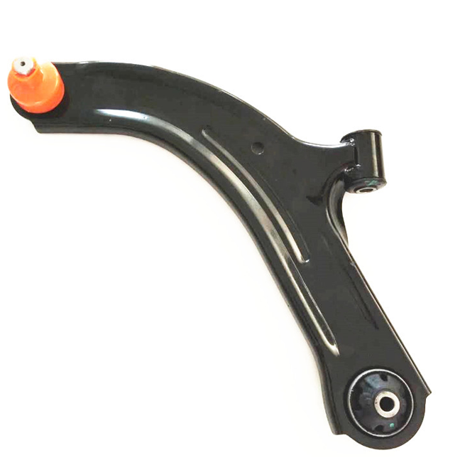
Apa itu lengan kawalan?
Bayangkan lengan kawalan sebagai anggota yang menyambungkan rangka kenderaan anda ke pemasangan rodanya. Pautan berengsel ini, often shaped like an 'A' or an 'I', ialah panduan utama untuk gerakan menegak roda (Pasukan Penyelidik CarParts.com & McCuistian, 2025). Apabila kereta anda mengalami bonggol atau tenggelam di jalan raya, roda bergerak ke atas atau ke bawah. Lengan kawalan memastikan pergerakan ini dikawal, membenarkan spring dan penyerap hentak melakukan tugas mereka menyerap hentaman sambil mengekalkan roda dalam orientasi yang betul berbanding dengan jalan dan badan kenderaan.
Dalam kebanyakan kenderaan penumpang moden, anda akan menemui lengan kawalan yang lebih rendah, dan dalam beberapa reka bentuk, terutamanya penggantungan double-wishbone, lengan kawalan atas juga. Lengan ini berputar pada sesendal di mana ia melekat pada subframe kenderaan, membolehkan lancar, artikulasi yang tenang. Hujung lengan yang lain, The "outboard" tamat, di situlah tumpuan kita, kerana di sinilah ia bertemu dengan sendi bola. Mendapatkan sumber yang berkualiti tinggi lengan kawalan selepas pasaran selalunya merupakan penyelesaian terbaik apabila komponen asal dibengkokkan, berkarat, atau telah memakai sesendal.
Peranan Utama Sendi Bola
Jika lengan kawalan ialah anggota badan, sendi bola ialah pergelangan tangan atau buku lali. Ia adalah galas sfera yang disertakan dalam soket, berfungsi sama seperti sendi bola dan soket dalam tubuh manusia. Reka bentuk ini bijak kerana ia membenarkan pergerakan dalam pelbagai satah. Ia membolehkan roda bergerak ke atas dan ke bawah dengan perjalanan penggantungan, sambil membenarkan ia berputar ke kiri dan ke kanan semasa anda mengemudi kenderaan (Customproc, 2025).
Sendi bebola terdiri daripada stud berulir yang disambungkan kepada bola logam, yang berputar di dalam pelincir, perumahan keluli. But getah mengelak sendi, melindunginya daripada kotoran, air, dan kotoran jalan sambil menyimpan gris penting di dalam. Stud sendi bebola bersambung ke buku jari stereng—komponen yang memegang hab roda dan galas. Sambungan ini biasanya padanan tirus, reka bentuk yang mencipta kunci mekanikal yang sangat kuat di bawah tekanan tetapi boleh menjadi punca kesukaran semasa pembongkaran.
Tekan masuk lwn. Sambungan Bola Bolt-on: Perbezaan Kritikal
Kaedah lampiran antara sambungan bola dan lengan kawalan itu sendiri adalah pembolehubah utama yang menentukan prosedur kami. Terdapat dua reka bentuk dominan yang akan anda temui.
- Sambungan Bola Bolt-on: Seperti namanya, ini diikat pada lengan kawalan dengan bolt atau, dalam beberapa kes, rivet. Mereka biasanya lebih mudah untuk diganti. Jika mereka menggunakan bolt, penyingkiran adalah perkara mudah untuk membukanya. Jika mereka menggunakan rivet, rivet mesti ditebuk atau dipahat, dan sambungan baru kemudiannya diikat dengan bolt yang dibekalkan.
- Sendi Bola Tekan Dalam: Ini adalah yang lebih biasa, dan lebih mencabar, reka bentuk. Di sini, perumah sambungan bola ditekan ke dalam lubang bulat yang dimesin dengan tepat di lengan kawalan dengan beribu-ribu paun daya. Ini mewujudkan kesesuaian gangguan, di mana sendi dipegang pada tempatnya oleh geseran yang besar. Mengalih keluar jenis ini memerlukan alat khusus untuk mengatasi daya itu. Percubaan untuk memalunya selalunya merupakan latihan yang sia-sia dan merosakkan.
Memahami jenis yang anda hadapi sebelum anda memulakan adalah penting. Pemeriksaan visual di mana sambungan bola bertemu dengan lengan kawalan akan mendedahkan sama ada kepala bolt/rivet atau licin, cincin logam lancar, yang menunjukkan reka bentuk press-fit.
Langkah 1: Persediaan dan Keselamatan – Asas Pembaikan yang Berjaya
Sebarang usaha mekanikal yang berjaya dibina bukan atas kekerasan, tetapi pada penyediaan kaedah. Masa yang dihabiskan di sini, sebelum satu bolt dipusing, adalah pelaburan yang membayar dividen dalam kecekapan dan, paling kritikal, dalam keselamatan diri. Bergegas ke dalam proses ini adalah resipi untuk benang yang dilucutkan, komponen yang rosak, dan kemungkinan kecederaan.
Mengumpul Arsenal Anda: Alat Penting & peralatan
Alat yang sesuai untuk pekerjaan itu bukanlah kemewahan; ia adalah satu keperluan. Percubaan untuk menggunakan alat yang salah adalah seperti cuba menulis novel dengan krayon—anda mungkin membuat markah, tetapi hasilnya akan menjadi kucar-kacir dan tidak dapat dibaca. Keperluan khusus anda akan berbeza sedikit berdasarkan kenderaan anda dan sama ada anda mempunyai sambungan tekan atau bolt-on, tetapi senarai teras kekal konsisten.
| Kategori Alat | Perkara Penting untuk Kedua-dua Jenis Sendi | Item Tambahan untuk Sendi Tekan Dalam |
|---|---|---|
| Mengangkat & Keselamatan | Jack Lantai, Jack Berdiri (sekurang-kurangnya 2), Tercekik Roda, Cermin Mata Keselamatan, Sarung Tangan Mekanik | – |
| Alatan Tangan | Set Soket (Metrik & SAE), Set Sepana, Bar Pemutus, Sepana Tork, penukul (Ball-peen & kereta luncur), Pry Bars | – |
| Alat Pemisahan | Acar Garpu (Pemisah Sendi Bola) ATAU Penarik Lengan Pitman | Tekan Sendi Bola (Gaya pengapit C) dengan Penyesuai |
| Penyingkiran Pengikat | – | Pengisar Sudut atau Pahat Udara (untuk sendi rivet) |
| Pembersihan | Berus Kawat, Pembersih Brek, Kedai Tuala | Kain Ampelas atau Kertas Pasir |
Bintang rancangan ini, untuk jenis press-in, ialah tekan sendi bola. Ini ialah alat C-clamp tugas berat yang disertakan dengan pelbagai lengan dan penyesuai. Ia menggunakan kelebihan mekanikal skru berulir besar untuk menjana daya besar yang diperlukan untuk menolak sambungan haus keluar dari lengan kawalan dan menekan yang baru ke dalam.. Walaupun ia mungkin kelihatan seperti pelaburan yang besar untuk satu pekerjaan, menyewa satu daripada kedai alat ganti kereta adalah pilihan biasa dan kos efektif.
Persediaan Kenderaan: Mengangkat dan Mengamankan
Persekitaran kerja anda mestilah stabil dan selamat. Kenderaan yang jatuh dari bicu adalah kegagalan besar yang boleh membawa maut.
- Park di Level Ground: Mulakan pada pepejal, permukaan rata seperti lantai garaj konkrit. Jangan sekali-kali bekerja di tanah lembut seperti asfalt pada hari yang panas, kotoran, atau rumput.
- Chock the Wheels: Sekat roda dengan selamat pada hujung bertentangan kenderaan dari tempat anda akan bekerja. Jika anda bekerja di hadapan, mencekik roda belakang.
- Longgarkan Kacang Lug: Sebelum mengangkat kenderaan, use a breaker bar to "break loose" kacang lug pada roda yang akan anda keluarkan. Jangan keluarkannya sepenuhnya, hanya mengatasi tork awal.
- Mengangkat: Letakkan bicu lantai anda di bawah titik angkat yang ditentukan pengeluar pada bingkai atau subframe kenderaan. Jangan sesekali bicu pada kuali minyak enjin, penularan, atau lengan kawalan itu sendiri. Naikkan kenderaan sehingga roda berada beberapa inci dari tanah.
- Letakkan Jack Stand: Ini adalah langkah keselamatan yang paling kritikal. Segera letakkan dirian bicu di bawah bahagian pepejal bingkai atau subbingkai berhampiran bicu. Turunkan kenderaan perlahan-lahan sehingga beratnya terletak sepenuhnya pada dirian bicu. Bicu ialah alat mengangkat, bukan peranti pegangan. Anda boleh membiarkan bicu di tempatnya sebagai sandaran kedua, tetapi tidak pernah bekerja di bawah kereta yang hanya disokong oleh bicu.
Keselamatan Diutamakan: Peralatan Pelindung Diri (PPE)
Proses bagaimana untuk mengeluarkan sambungan bebola dari lengan kawalan melibatkan logam memukul, berurusan dengan bahagian yang berkarat, dan potensi spring atau komponen untuk membebaskan tenaga. Lindungi diri anda dengan sewajarnya.
- Cermin Mata Keselamatan: Tidak boleh dirunding. Serpihan logam, serpihan karat, atau percikan pembersih brek di mata boleh menyebabkan kerosakan kekal.
- Sarung Tangan Mekanik: Lindungi tangan anda daripada luka, goresan, dan kotoran. Mereka juga meningkatkan cengkaman anda pada alatan.
- Kasut Teguh: But berujung keluli sangat sesuai. Lengan kawalan yang terjatuh atau alat berat boleh mematahkan tulang di kaki anda dengan mudah.
Langkah 2: Mendapat Akses – Membongkar Pemasangan Roda dan Brek
Dengan kenderaan disokong dengan selamat, objektif kami seterusnya adalah untuk mengosongkan laluan ke lengan kawalan dan sendi bola. Ini melibatkan pembongkaran roda yang teliti dan teratur, brek, dan komponen stereng yang berkaitan. Anggaplah ia seperti mengupas lapisan bawang untuk sampai ke inti.
Menanggalkan Komponen Roda dan Brek
Organisasi adalah kunci di sini. Semasa anda mengeluarkan bolt dan bahagian, letakkannya dalam dulang magnetik atau bekas berlabel. Tabiat mudah ini menghalang carian terburu-buru untuk bolt caliper yang hilang di kemudian hari.
- Keluarkan Roda: Dengan kacang lug yang sudah dilonggarkan, anda kini boleh memutarkannya dengan tangan dan mengeluarkan roda. Ketepikan.
- Tanggalkan Angkup Brek: Cari dua pin panduan angkup atau bolt pelekap di belakang buku jari stereng. Mereka biasanya dilindungi oleh penutup habuk getah. Tanggalkan bolt ini. Jangan biarkan caliper bergantung pada hos breknya. Ini boleh merosakkan hos, membawa kepada kegagalan brek. Gunakan kord bungee atau sekeping wayar untuk menggantung angkup dengan selamat dari tupang atau anggota bingkai.
- Tanggalkan Pendakap Caliper (jika perlu): Dalam beberapa reka bentuk, pendakap caliper juga mungkin perlu ditanggalkan untuk mengakses komponen lain. Ia dipegang oleh dua bolt yang lebih besar di bahagian belakang buku jari stereng.
- Keluarkan Pemutar Brek: Pemutar kini harus meluncur keluar dari hab roda. Jika ia tersekat kerana karat, beberapa ketukan kukuh dengan tukul pada permukaan yang menghadap hab boleh membantu memecahkannya. Berhati-hati untuk tidak memukul permukaan brek itu sendiri.
Memutuskan Sambungan Pautan Penstabil dan Hujung Batang Pengikat
Sekarang kita beralih ke yang lebih kecil, tetapi sama pentingnya, penggantungan dan pautan stereng.
- Pautan Bar Penstabil: Rod nipis ini menyambungkan hujung bar penstabil (atau bar bergoyang) ke lengan kawalan atau tupang. Tugasnya ialah mengawal guling badan semasa berpusing (AutohausAZ, 2025). Ia biasanya dipegang dengan kacang di bahagian atas dan bawah. Anda mungkin perlu menggunakan sepana untuk memegang stud itu sendiri semasa anda memutar nat untuk mengelakkannya daripada berputar.
- Hujung Batang Pengikat Luar: Ini adalah sebahagian daripada sistem stereng. Ia menyambungkan rak stereng ke buku jari stereng. Menanggalkan nat penahannya dan mengasingkan stud tirusnya daripada buku jari adalah langkah yang perlu. Proses ini adalah sama dengan memisahkan sendi bebola utama dari buku jari, yang akan kami bincangkan dengan terperinci dalam langkah seterusnya.
Pada ketika ini, anda harus mempunyai pandangan yang jelas tentang lengan kawalan, buku jari stereng, dan sendi bola yang menghubungkan mereka. Pentas ditetapkan untuk bahagian pembongkaran yang paling mencabar.
Langkah 3: Detik Penting – Memisahkan Sendi Bola daripada Buku Jari Steering
Di sinilah selalunya kerja mudah boleh bertukar menjadi pertempuran kehendak. Sambungan antara stud tirus sambungan bola dan buku jari stereng direka bentuk dengan sangat selamat. Selama bertahun-tahun perkhidmatan, panas, tekanan, dan kakisan membentuk ikatan yang sangat degil untuk dipecahkan. Kuncinya ialah menggunakan teknik yang betul untuk mengejutkan sambungan yang longgar tanpa menyebabkan kerosakan cagaran.
Cabaran Stud Tirus
Mengapa hubungan ini sukar untuk dipisahkan? Stud tirus sesuai dengan lubang tirus yang sepadan. Sebagai kacang penahan (biasanya kacang istana dengan pin cotter) diketatkan, ia menarik stud lebih dalam ke dalam lubang, mewujudkan jumlah geseran yang besar dan kunci mekanikal. Ia adalah kesesuaian akhbar, tetapi yang berbentuk kon. Hanya mengeluarkan kacang tidak membantu untuk melegakan tekanan ini. Anda tidak boleh memisahkannya begitu saja. Daya mesti digunakan dengan cara yang memecahkan kunci geseran ini.
Sebelum anda bermula, sapukan minyak penembus yang berkualiti (seperti PB Blaster atau Kroil) ke kawasan di mana stud melepasi buku jari. Biarkan ia duduk sekurang-kurangnya 15-30 minit, atau bahkan semalaman jika anda boleh. Ini akan membantu membubarkan karat dan memudahkan proses pengasingan.
Kaedah A: Garpu Acar (Pemisah Sendi Bola)
Garpu acar adalah serampang dua mata, alat berbentuk baji. Ia direka untuk dipandu antara buku jari stereng dan perumah sambungan bebola, memaksa mereka berpisah.
- Cara Menggunakannya: Selepas mengeluarkan kacang istana, benangnya kembali pada beberapa pusingan untuk melindungi benang stud. Masukkan tali garpu acar di antara but getah sendi bebola dan buku jari stereng. Kemudian, menggunakan tukul besar atau tukul kecil, pukul hujung garpu acar dengan kuat.
- Kebaikan: Ia selalunya berkesan dan agak murah.
- Keburukan: This is the "brute force" kaedah. Ia hampir pasti akan memusnahkan but getah sendi bola, bermakna anda mesti menggantikan sambungan bola jika anda menggunakan alat ini. Ia juga berpotensi merosakkan buku jari stereng atau lengan kawalan jika tidak digunakan dengan berhati-hati atau jika bahagian itu dirampas dengan teruk. Ia adalah alat komitmen; tiada berpatah balik apabila anda menggunakannya.
Kaedah B: Teknik Tukul
Kaedah ini kelihatan berlawanan dengan intuisi, tetapi selalunya teknik ini menjadi pilihan juruteknik profesional kerana ia kurang berkemungkinan merosakkan komponen lain apabila dilakukan dengan betul. Ia menggunakan prinsip kejutan hidraulik untuk memecahkan kesesuaian tirus.
- Cara Menggunakannya: Keluarkan kacang istana sepenuhnya. Ambil tukul berat (a 2-3 lb kereta luncur adalah ideal) dan menyampaikan beberapa tajam, pukulan kuat terus ke tepi buku jari stereng di mana stud sendi bola melepasi. Anda tidak memukul stud itu sendiri, but the "eye" buku jari yang mengelilinginya.
- Mengapa Ia Berfungsi: Logam buku jari stereng adalah anjal sedikit. Daya pukulan tukul mencacatkan seketika bentuk lubang tirus itu, memecahkan kunci geseran dan menyebabkan stud terkeluar.
- Kebaikan: Apabila berjaya, ia pantas dan tidak merosakkan but sendi bola (berguna jika anda menanggalkan buku jari untuk pembaikan lain dan merancang untuk menggunakan semula sendi bebola). Ia mengarahkan daya hanya pada buku jari, meminimumkan risiko kepada bahagian kawalan.
- Keburukan: Ia memerlukan keyakinan dan kekuatan, hayunan tepat. Ia mungkin tidak berfungsi pada sendi yang sangat dirampas. Terdapat risiko hilang dan terkena plat pemutar brek atau komponen lain.
Kaedah C: Penarik Lengan Pitman / Alat Pemisah Sendi Bola
This is the most controlled and arguably the "correct" cara untuk melakukan pemisahan. Alat ini menggunakan leverage mekanikal untuk menekan stud keluar dari buku jari.
- Cara Menggunakannya: Alat ini datang dalam pelbagai reka bentuk, tapi prinsipnya sama. Alat ini diposisikan supaya satu bahagian menolak ke bawah pada hujung stud sendi bebola manakala bahagian yang lain cangkuk di bawah buku jari stereng. Semasa anda mengetatkan bolt pada alat, ia menjana yang berkuasa, daya tekan mantap yang menolak stud keluar dari tempat duduknya yang tirus.
- Kebaikan: Ia adalah kaedah yang paling selamat dan terkawal. Ia sangat tidak mungkin menyebabkan kerosakan pada stud, but, atau buku jari.
- Keburukan: Ia memerlukan alat yang betul, yang mungkin merupakan perbelanjaan tambahan atau sewa. Kadangkala sukar untuk meletakkan alat dengan betul dalam ruang yang sempit.
| Kaedah Pemisahan | Keberkesanan | Risiko Kerosakan | Kos Alat | Kes Penggunaan Terbaik |
|---|---|---|---|---|
| Acar Garpu | Tinggi | Tinggi (memusnahkan but) | Rendah | Apabila anda pasti menggantikan sambungan bola dan kaedah lain gagal. |
| Teknik Tukul | Sederhana hingga Tinggi | Rendah (jika dilakukan dengan betul) | Sangat Rendah | Pemisahan pantas apabila anda ingin mengekalkan but sendi bola. |
| Penarik/Pemisah | Sangat tinggi | Sangat Rendah | Sederhana hingga Tinggi | Yang paling selamat, kaedah paling profesional untuk sebarang keadaan, terutamanya sendi yang degil. |
Sebaik sahaja stud terlepas dari buku jari, anda boleh meneruskan ke langkah seterusnya. Anda mungkin perlu menggunakan bar pry untuk menolak lengan kawalan ke bawah sedikit untuk mencipta kelegaan yang mencukupi untuk memisahkan sepenuhnya kedua-dua komponen.
Langkah 4: Mengasingkan Komponen – Menanggalkan Lengan Kawalan daripada Kenderaan
Dalam banyak kes, terutamanya dengan sendi bola tekan dalam, cara yang paling berkesan untuk melaksanakan perkhidmatan adalah dengan mengeluarkan keseluruhan lengan kawalan dari kenderaan. Ini membolehkan anda membawanya ke meja kerja di mana anda mempunyai akses yang lebih baik, leverage, dan keupayaan untuk menggunakan ragum bangku dan penekan sambungan bola dengan lebih berkesan. Walaupun kadang-kadang mungkin untuk menekan sendi keluar semasa lengan masih berada di atas kereta, ia selalunya lebih sukar dan memakan masa.
Mencari dan Melonggarkan Bolt Lengan Kawalan
Lengan kawalan biasanya dipasang pada subframe kenderaan pada dua titik melalui bolt besar yang melalui sesendal getah.
- Pemeriksaan dan Minyak Penembusan: Sebelum anda bermula, cari bolt ini. One is usually at the "front" of the control arm and the other at the "rear". Mereka boleh berorientasikan secara menegak atau mendatar. Seperti setiap pengikat lain dalam persekitaran berkarat ini, berilah mereka rendaman yang banyak dalam minyak tembus.
- Gunakan Bar Pemutus: Bolt ini selalunya sangat ketat dan mungkin mempunyai sebatian pengunci benang padanya dari kilang. Bar pemutus panjang akan menjadi kawan baik anda di sini. Letakkan soket dan bar pemutus anda dengan selamat pada kepala bolt atau nat.
- Fikirkan Alignment Cams: Beri perhatian kepada bolt. Kadang-kadang, one or both of the control arm mounting bolts will have an eccentric washer or "cam" pada mereka. Ini digunakan untuk melaraskan penjajaran roda kenderaan (kastor atau camber). Jika anda melihat satu, adalah amalan yang baik untuk menggunakan penanda cat atau juru tulis untuk menandakan kedudukan sesondol berbanding dengan subframe sebelum anda melonggarkannya. This will allow you to get the alignment "close enough" apabila dipasang semula untuk memandu kenderaan dengan selamat ke kedai penjajaran.
Menghalang Halangan (gandar, Subframe)
Bergantung pada reka bentuk kenderaan anda, menanggalkan bolt lengan kawalan mungkin bukan perkara yang mudah.
- Kenderaan Pacuan Roda Depan: Pada kereta FWD, aci gandar CV selalunya melepasi terus atau melalui kawasan lengan kawalan. Anda mungkin perlu berhati-hati menggerakkan knuckle stereng dan pemasangan topang untuk mencipta kelegaan yang mencukupi untuk meluncurkan bolt lengan kawalan panjang keluar.
- Gangguan Subframe: Kadang-kadang, subframe itu sendiri boleh menyekat laluan bolt. Dalam kes-kes yang mengecewakan ini, anda mungkin perlu menurunkan sedikit satu sisi subframe dengan melonggarkan bolt pelekap utamanya untuk mencipta kelegaan yang diperlukan. Rujuk manual servis untuk kenderaan khusus anda jika anda menghadapi situasi ini, kerana ia menambahkan lapisan kerumitan yang ketara kepada kerja.
Penyingkiran Akhir Lengan Kawalan
Sebaik sahaja dua bolt pemasangan dalam dikeluarkan dan sambungan bola luar bebas daripada buku jari stereng, lengan kawalan boleh digoyang-goyangkan dan dilepaskan dari kenderaan. Ia mungkin lebih berat daripada yang anda jangkakan, jadi bersiaplah untuk menyokong beratnya apabila ia longgar. Sekarang, anda boleh membawanya ke meja kerja anda untuk operasi utama.
Langkah 5: Acara Utama – Cara Mengeluarkan Sendi Bola Dari Lengan Kawalan
Dengan lengan kawalan pada meja kerja anda, anda mempunyai ruang dan kestabilan untuk menangani tugas teras. Kaedah di sini menyimpang sepenuhnya berdasarkan sama ada anda mempunyai sambungan tekan atau bolt-on.
Untuk Sendi Bola Tekan Dalam: Menggunakan Ball Joint Press
Di sinilah alat penekan C-clamp khusus memperoleh simpanannya. Matlamatnya adalah untuk menggunakan gabungan penyesuai yang betul untuk menolak sambungan lama keluar dari lubangnya tanpa merosakkan lengan kawalan.
- Selamatkan Lengan Kawalan: Letakkan lengan kawalan dengan selamat dalam ragum bangku tugas berat. Jika anda tidak mempunyai ragum, anda boleh bekerja di atas lantai, tetapi ia akan menjadi lebih sukar untuk memastikan keadaan stabil.
- Keluarkan Cincin Snap: Periksa sendi bola. Banyak sambungan tekan-dalam mempunyai cincin snap (atau lilitan) pada satu sisi yang bertindak sebagai penahan sekunder. Anda mesti mengeluarkan cincin snap ini sebelum cuba menekan sambungan keluar. Gunakan sepasang tang cincin snap yang baik untuk ini.
- Konfigurasikan Akhbar: Ini adalah bahagian paling penting dalam mempelajari cara menanggalkan sambungan bola dari lengan kawalan dengan penekan. Anda perlu memilih penyesuai yang betul.
- Tiub Penerimaan: Pilih penyesuai berongga (tiub penerima) yang cukup besar untuk dilalui oleh badan sendi bola. Ia mesti terletak tepat pada lengan kawalan di sekeliling tepi sendi bola, bukan pada sendi itu sendiri. Tiub ini mencipta ruang kosong untuk sendi lama ditolak.
- Menekan Penyesuai: Di seberang sana, pilih penyesuai pepejal atau berongga yang cukup kecil untuk menekan badan sendi bebola itu sendiri, tetapi tidak terlalu kecil sehingga tergelincir ke dalam atau hanya menolak pada stud. Anda ingin menggunakan daya pada bebibir luar sambungan yang kuat.
- Letakkan Alat: Pasang penekan C-clamp di sekeliling lengan kawalan dengan tiub penerima di sisi sambungan akan keluar dari, dan penyesuai penekan di sebelah anda akan menolak. Pastikan semuanya betul-betul lurus dan berpusat. Penekan yang bengkok boleh merosakkan lubang lengan kawalan.
- Gunakan Daya: Menggunakan sepana besar atau palang pemutus, mula mengetatkan skru utama akhbar. Daya yang diperlukan akan menjadi sangat besar. Anda mungkin akan mendengar rintihan dan bunyi yang kuat apabila geseran padanan gangguan diatasi. Teruskan mengetatkan sehingga sambungan bola lama ditolak sepenuhnya keluar dari lengan kawalan dan ke dalam tiub penerima.
Untuk Sendi Bola Bolt-on: Penyingkiran Lebih Mudah
Jika anda bernasib baik untuk mempunyai sambungan bolt-on, prosesnya jauh kurang dramatik.
- Jenis Bolted: Hanya gunakan soket atau sepana yang sesuai untuk menanggalkan bolt yang menahan sambungan bola ke lengan kawalan. Jika bolt berkarat, gunakan minyak tembus dan berhati-hati agar tidak membulatkan kepala.
- Jenis Rivet: Sambungan bolt-on yang dipasang di kilang sering menggunakan rivet dan bukannya bolt. Ini mesti dimusnahkan untuk dialih keluar. Kaedah yang paling biasa ialah:
- menggerudi: Gunakan penebuk tengah untuk menandakan pusat setiap rivet. Mulakan dengan mata gerudi kecil dan secara beransur-ansur naik ke bit yang sama saiz dengan batang rivet. Ini akan menggerudi kepala, membolehkan anda menebuk seluruh rivet keluar.
- Mengisar/Memanas: Gunakan pengisar sudut untuk mengisar kepala dari rivet. Sebagai alternatif, tukul udara dengan bit pahat boleh membuat kerja cepat mencukur kepala rivet. Sentiasa pakai cermin mata keselamatan dan berhati-hati terhadap percikan api apabila menggunakan penggiling.
Sebaik sahaja pengikat dikeluarkan, sendi bola hanya akan mengangkat lengan kawalan.
Langkah 6: The Rebirth – Memasang Ball Joint Baharu
Mengeluarkan bahagian lama hanya separuh daripada pertempuran. Pemasangan yang betul adalah sama pentingnya untuk pembaikan yang tahan lama dan selamat.
Membersih dan Menyediakan Lengan Kawalan
Sama ada tekan masuk atau bolt-on, permukaan pelekap pada lengan kawalan mestilah bersih dengan sempurna.
- Untuk Press-in: Gunakan berus dawai dan pembersih brek untuk membersihkan bahagian dalam lubang di lengan kawalan dengan teliti. Periksa ia untuk sebarang burr, gouges, atau kerosakan yang mungkin berlaku semasa penyingkiran. Jika terdapat sedikit ketidaksempurnaan, anda boleh menggunakan sekeping kain ampelas atau kertas pasir halus untuk melicinkannya. Sendi baru bergantung pada yang bersih, permukaan licin untuk kesesuaian gangguan yang betul.
- Untuk Bolt-on: Bersihkan permukaan pelekap rata pada lengan kawalan di mana sendi baru akan duduk. Pastikan ia bebas daripada karat dan serpihan supaya sambungan baharu boleh terduduk dengan sempurna.
Menekan dalam Sendi Bola Baharu
Pemasangan adalah kebalikan daripada penyingkiran, tetapi memerlukan penjagaan dan ketepatan yang sama dengan penekan sambungan bola.
- Perhatikan Arah: Beberapa sendi bola adalah arah. Mereka mungkin mempunyai orientasi tertentu atau pelepasan yang perlu diselaraskan dengan bahagian tertentu lengan kawalan. Semak bahagian baharu dan manual servis.
- Konfigurasikan Akhbar untuk Pemasangan: Anda sekali lagi akan menggunakan tiub penerima dan penyesuai menekan. Kali ini, tiub penerima akan menyokong bahagian belakang lengan kawalan, dan anda akan menekan bahagian bawah rata sendi bola baru. Jangan sekali-kali tekan pada stud tirus.
- Mulakannya Lurus: Ia boleh membantu untuk mengetuk ringan sendi baharu dengan tukul untuk memulakannya terus di dalam lubang sebelum menggunakan penekan. Salutan gris atau anti rampas yang sangat ringan pada bahagian luar sambungan baharu boleh memudahkan pemasangan, tetapi semak arahan pengeluar kerana sesetengah orang menasihatkannya.
- Tekan Laman Utama: Berhati-hati meletakkan penekan dan mula mengetatkan skru. Perhatikan dengan teliti untuk memastikan sambungan berjalan lurus dengan sempurna. Jika ia mula menjalar ke sebelah, undur dan tetapkan semula. Teruskan menekan sehingga bebibir sambungan bola baru didudukkan dengan kukuh dan sepenuhnya pada lengan kawalan.
- Pasang Cincin Snap Baharu: Jika sendi baru anda datang dengan cincin snap, pasang sekarang. Juga, pastikan anda memasang pemasangan gris baharu (jika dibekalkan) dan isikan sendi dengan gris yang disyorkan sehingga but getah mula membengkak.
Mengamankan Sambungan Bola Bolt-on
Ini adalah lebih mudah. Letakkan sambungan bola baharu pada permukaan pelekap bersih lengan kawalan. Masukkan bolt gred tinggi baharu (yang harus disertakan dengan sendi) dan ketatkan mereka. Adalah penting untuk menggunakan sepana tork untuk mengetatkan bolt ini kepada nilai yang ditentukan pengeluar. Selalunya, kit ini juga akan termasuk kacang pengunci baharu.
Langkah 7: Perhimpunan semula, Tork, dan Penjajaran – Memulihkan Ketenteraman
Dengan sambungan bola baru dengan selamat di lengan kawalan, sudah tiba masanya untuk menyusun semula segala-galanya. Proses ini pada asasnya adalah kebalikan daripada pembongkaran, tetapi dengan tumpuan kritikal pada tork yang betul.
Memasang semula Lengan Kawalan dan Pemasangan Roda
- Pasang semula Lengan Kawalan: Alihkan lengan kawalan kembali ke kedudukannya dan masukkan bolt pelekap dalam. Jika anda membuat tanda penjajaran, cuba bariskan mereka sebaik mungkin. Benang kacang tetapi jangan ketatkan sepenuhnya lagi. Sesendal suspensi hendaklah sentiasa dikilas dengan berat kenderaan padanya, bukan semasa tergantung di udara.
- Sambungkan Sendi Bola ke Knuckle: Bimbing stud sendi bola baharu melalui buku jari stereng. Pasang nat istana baharu dan ketatkannya mengikut tork yang ditentukan. Jika stud berputar, anda mungkin perlu menggunakan tekanan ke atas pada lengan kawalan dengan bicu untuk mencipta geseran yang mencukupi untuk mengetatkan nat. Selaraskan slot dalam nat dengan lubang pada stud dan masukkan pin cotter yang baru, bengkokkan hujung untuk mengamankannya.
- Pengetatan Akhir: Dengan lengan kawalan dan buku jari disambungkan, letakkan bicu lantai anda di bawah lengan kawalan dan naikkannya sehingga ia mula mengangkat berat kenderaan dari dudukan bicu. Ini menyerupai ketinggian tunggangan biasa. Sekarang, anda boleh menggunakan sepana tork anda untuk mengetatkan bolt pelekap lengan kawalan dalam mengikut spesifikasi akhir mereka.
- Pasang semula Brek dan Roda: Pasang semula hujung batang pengikat luar, pautan penstabil, pemutar brek, angkup brek, dan roda. Tork semua pengikat kepada nilai yang ditentukan, terutamanya bolt caliper dan nat lug.
Kepentingan Penjajaran Roda Selepas Pembaikan
Langkah terakhir ini bukan pilihan. Setiap kali anda menggantikan komponen penggantungan utama seperti lengan kawalan atau sendi bebola, anda mengubah geometri penggantungan kenderaan (Timing-Parts.com, 2025). Walaupun anda menandakan bolt cam, ia tidak cukup tepat.
Memandu kenderaan dengan penjajaran yang tidak betul akan menyebabkan kehausan tayar yang cepat dan tidak rata, ciri pengendalian yang lemah, dan boleh menjadi tidak selamat. Selepas selesai pembaikan, anda mesti membawa kenderaan ke kedai profesional untuk melakukan penjajaran empat roda. Ini memastikan bahawa camber, caster, dan sudut kaki semuanya ditetapkan kembali kepada spesifikasi tepat pengeluar, memulihkan pengendalian kenderaan, keselamatan, dan memanjangkan hayat tayar baharu anda dan komponen penggantungan.
Soalan yang sering ditanya (Soalan Lazim)
Bolehkah saya hanya memalu sambungan bola tekan keluar dari lengan kawalan? Walaupun ia mungkin menggoda, ia amat dinasihatkan supaya tidak. Kesesuaian gangguan sangat ketat. Memalu terus pada sendi bola boleh merosakkan lengan kawalan dengan memesongkan gerek, menjadikannya mustahil untuk sambungan baru untuk dimuatkan dengan betul. Ia juga merupakan kaedah yang tidak berkesan dan mengecewakan yang sering gagal. Menggunakan penekan sambungan bola yang betul adalah cara yang betul dan paling selamat.
Adakah saya perlu menggantikan keseluruhan lengan kawalan dan bukannya sendi bola sahaja? Bukan selalu, tetapi ia menjadi lebih biasa. Banyak pengeluar kini menyediakan bahagian kawalan sebagai pemasangan lengkap, dengan sesendal baharu dan sambungan bola baharu telah dipasang. Ini boleh menjimatkan masa buruh yang ketara dan memastikan semua item haus yang berkaitan adalah baharu. Jika sesendal lengan kawalan anda juga haus, atau jika lengan itu sendiri bengkok atau sangat terhakis, menggantikan keseluruhan pemasangan lengan kawalan adalah pembaikan yang unggul.
Apakah tanda-tanda sendi bola yang tidak baik? Gejala biasa termasuk bunyi ketukan atau ketukan dari ampaian hadapan, terutamanya apabila melepasi benjolan atau berpusing; stereng yang tidak jelas atau berkeliaran; dan memakai tayar yang tidak sekata, terutamanya pada bahagian tepi dalam atau luar. Sendi bebola yang haus teruk boleh berpisah sepenuhnya, menyebabkan bencana kehilangan kawalan kenderaan.
Berapa lama masa yang diambil untuk mengeluarkan sendi bebola daripada lengan kawalan? Untuk DIYer berpengalaman atau profesional dengan alatan yang betul, keseluruhan proses (daripada mengangkat kereta hingga selesai memasang semula) boleh ambil 2-4 jam setiap sisi. Walau bagaimanapun, jika anda menemui pengikat yang berkarat teruk atau sambungan tekan muat yang degil, ia boleh mengambil masa yang lebih lama. Kesabaran adalah kunci.
Adakah penjajaran roda benar-benar diperlukan selepas menggantikan sendi bola? Ya, secara mutlak. Kedudukan sambungan bola adalah titik rujukan kritikal untuk geometri ampaian kenderaan. Menggantikannya, atau lengan kawalan, sudah pasti akan menukar sudut camber dan/atau kaki. Melangkau penjajaran akan membawa kepada pengendalian yang lemah, ciri pemanduan yang tidak selamat, dan akan cepat merosakkan tayar anda.
Pemikiran Akhir tentang Proses
Perjalanan bagaimana untuk mengeluarkan sambungan bebola dari lengan kawalan adalah pengalaman pembaikan automotif yang sangat penting. Ia adalah satu proses yang memerlukan gabungan perancangan yang teliti, alatan yang betul, kekerasan yang digunakan dengan ketepatan, dan penghormatan yang mendalam terhadap keselamatan dan prosedur. Ia boleh menjadi pertempuran yang mengecewakan terhadap karat dan bahagian yang dirampas, tetapi perasaan pencapaian apabila sendi baru duduk, dan kenderaan itu ketat, stereng responsif dipulihkan, adalah besar. Pembaikan ini lebih daripada sekadar menggantikan bahagian; ia adalah penglibatan intim dengan kuasa yang memastikan kenderaan sentiasa bersambung ke jalan raya, pengajaran langsung dalam kejuruteraan sistem penggantungan moden yang elegan dan mantap.
Rujukan
AutohausAZ. (2025). Sistem stereng dan sistem suspensi: Bagaimana untuk mengekalkan & membaiki mereka. Diambil dari
Pasukan Penyelidik CarParts.com, & McCuistian, R. (2025). Apa yang dilakukan oleh senjata kawalan? Carparts.com. Diambil dari https://www.carparts.com/blog/what-do-control-arms-do/
Customproc. (2025). Panduan muktamad untuk bahagian penggantungan kereta. Diambil dari
Mihmidati, N. W. (2024). Tinjauan lebih mendalam tentang pelbagai komponen sistem suspensi kereta dan fungsinya. TransTRACK. Diambil dari https://blog.transtrack.co/en/technology/car-suspension-system-components/
Timing-Parts.com. (2025). 10 jenis klasifikasi sistem penggantungan kereta. Diambil dari
Zhejiang ZG Car Parts Co., Ltd. (2025). Panduan komprehensif untuk senjata kawalan kenderaan. Alat Ganti Kereta ZG. Diambil dari https://www.zgcarparts.com/media/a-comprehensive-guide-to-vehicle-control-arms.html